Determining the Correct Position for Stolspeed VGs
The VGs should be positioned to get the best ‘bite’ on the airflow when the wing is at the stall angle of attack. If they are too far aft, they risk being buried in the thickening boundary layer and the start of separation, so they lose effectiveness at stall. You can read more about my flight testing to determine the best positioning in the Frequently Asked Questions.
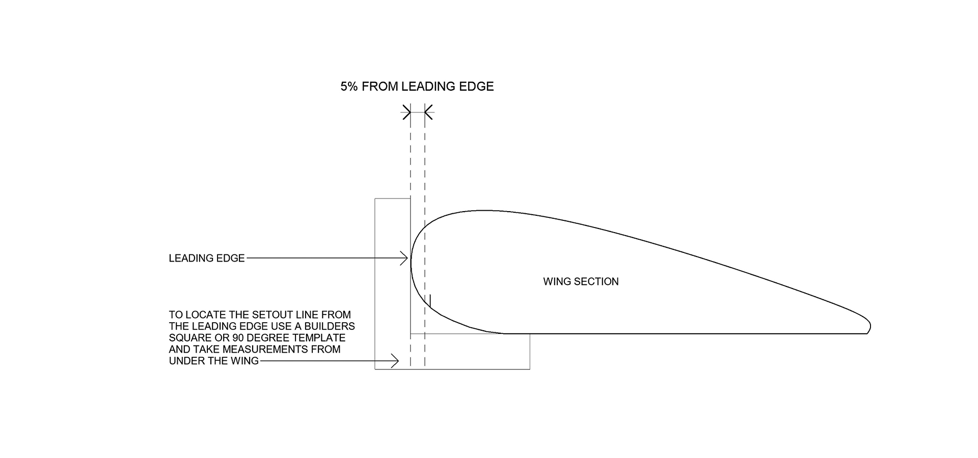
I recommend placing the VGs with their front tips at 5% of the chord length back from the leading edge. 120 VGs will be enough to do 9.9 metres (32ft) wing.
First, you will need to measure the chord depth from the leading edge to the aft edge of the ailerons or flaps. If the aircraft has detached flaperons, measure to the aft edge of the main wing.
- Use a builder’s square to locate the leading edge of the wing. If you don't have a builders square, you can cut a cardboard template that gives you a 90 degree angle as shown below.
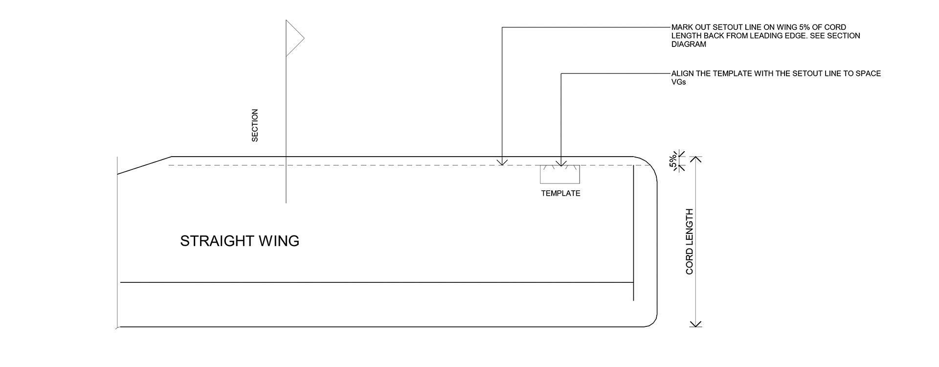
For a Straight Wing:
- Mark a line 5% of the chord length back from the leading edge using the builder’s square
- Stretch a straight string line along the wing at the 5% measurement and secure it with masking tape.
- Use the template provided to accurately place the VG with the front tips along this 5% line.
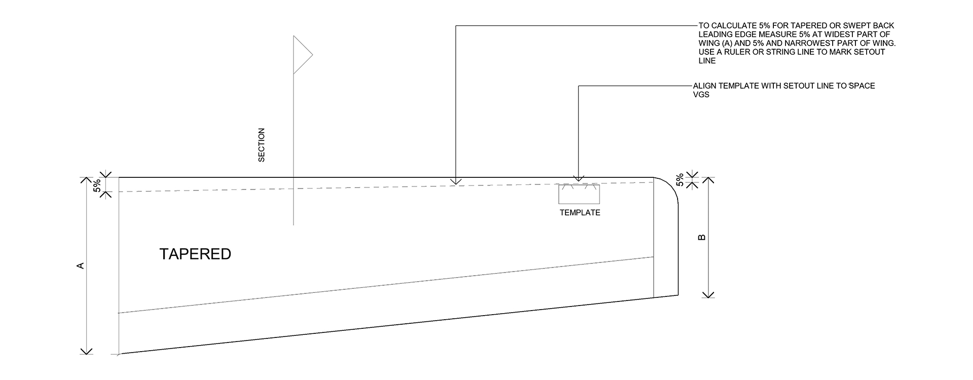
For a Tapered Wing
1. Measure the chord at both the wing root and tip.
2. Calculate 5% of the chord at each point and stretch a string line between these two measurements to mark the 5% line.
3. Use the template provided to accurately place the VG with the front tips along this 5% line.
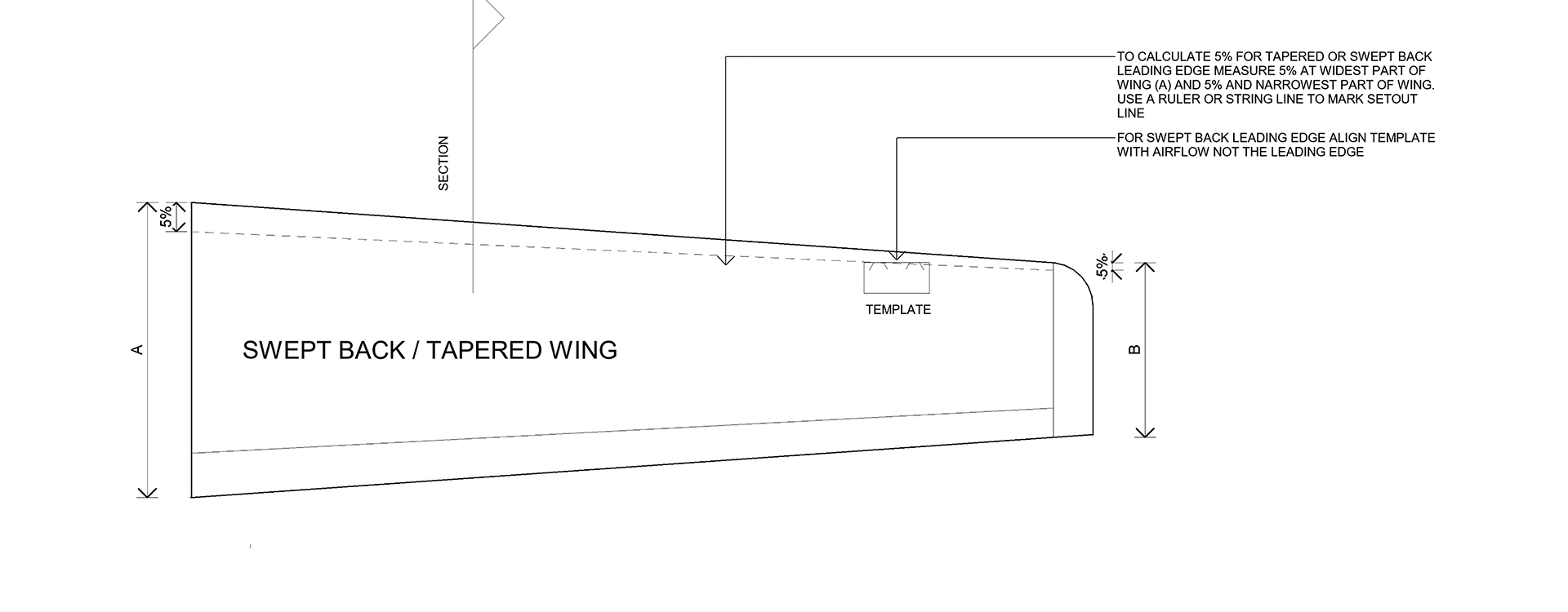
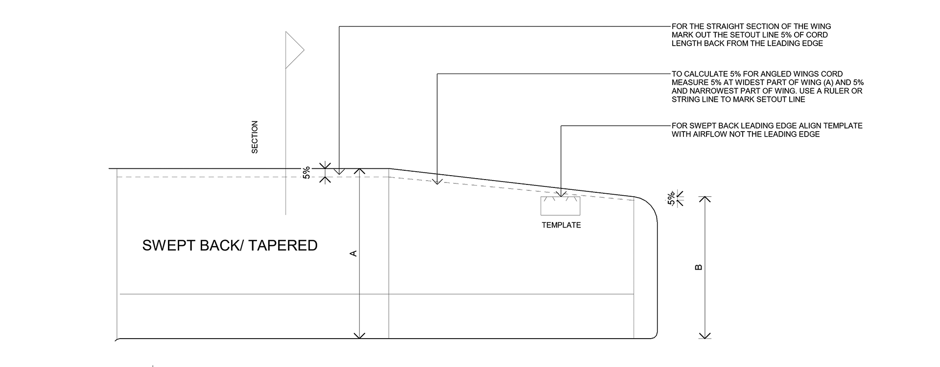
For a Tapered Wing With a Swept-Back Leading Edge:
Since the VGs need to be oriented with respect to the airflow rather than the leading edge, a slightly different procedure is needed with a swept-back leading edge. The VGs are effective at angles from 10º to 20º, so setting them at 15º allows for best margin of variable airflow. So we need to orient the template at right angles to the expected airflow.
1. Measure the chord at both the wing root and tip.
2. Calculate 5% of the chord at each point and stretch a string line between these two measurements to mark the 5% line.
3. Once you have marked the 5% line, align the spacing template at 90º to the airflow, not parallel to the string line.
4. Place the VG with front tip at the line, but orient the template at 90 degrees to the airflow rather than along the string line.
Placing the Vortex Generators (VGs) on the Wing Using the Template
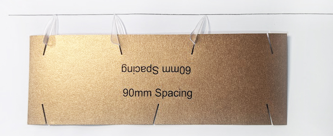
Each kit contains three spacing templates: 30mm, 60mm and 90mm. The 60mm template is used to position the first 15 VGs from the wingtip, while the 90mm template is used for the remaining VGs along the wing. The closer spacing near the wingtip helps prevent tip stall. The 30mm template will be used for placement on the horizontal stabilizer and vertical fin.
-
Starting 50mm (2") from each wing tip, align the template perpendicular to the airflow
-
Remove the adhesive backing from a VG and set the first VG in the notches on the 60mm template.
-
Lightly touch the VG tip just behind the marked line, then lower the base, guided by the template. Check alignment, then press down firmly. Use a thumbnail or popsicle stick to rub each side of the base to remove any air bubbles.
-
Use the next two notches to place two more VGs.
-
Shift the template so the last VG set is aligned with the third notch, then continue placing two at a time. (Note: Current templates have four notches.)
After placing the first 15 VGs with the 60mm template, switch to the 90mm template and continue using the same method for the rest of the wing.
Note: If a VG lands on a rivet or seam, shift it slightly to avoid the obstacle, then resume the normal spacing.